NASA’s Space Communications and Navigation (SCaN) program is developing capabilities that will allow missions at high altitudes to take advantage of GNSS signals for timing and navigation, including the Artemis missions to the Moon.
Interoperability of the GNSS constellations will be key for spacecraft at higher altitudes where GNSS signals are less plentiful. The program will rely on the four global constellations (GPS, Galileo, GLONASS and BeiDou) and the two regional systems operated by India and Japan.
SCaN is supporting flight experiments that will help develop multi-GNSS capabilities for spacecraft, such as Bobcat-1, developed by NASA’s Glenn Research Center in Cleveland and Ohio University.
Bobcat on the Prowl
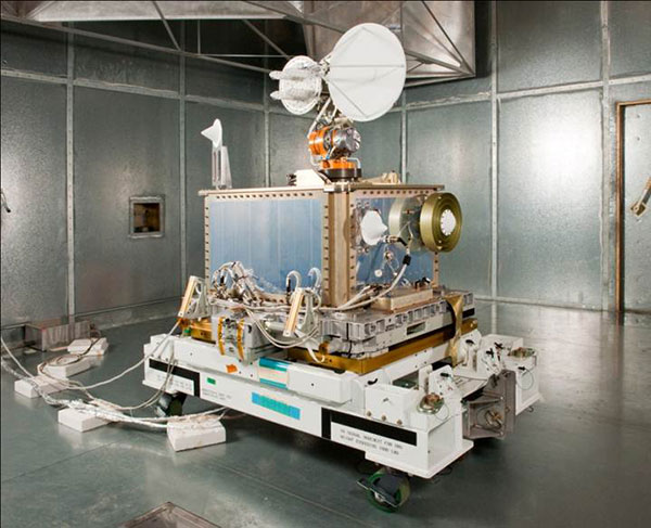
Bobcat-1, shown with its deployable antenna stowed, will experiment with the GNSS inter-constellation time offset from low-Earth orbit. (Photo: NASA)
Bobcat-1 was selected by the CubeSat Launch Initiative in 2018 to study GNSS signals from 250 miles overhead. The small satellite launched to the International Space Station aboard a Northrop Grumman Cygnus spacecraft on Oct. 2, 2020.
On Nov. 5, the space station released the CubeSat to begin its mission. The spacecraft will orbit for about nine months, measuring signals from different GNSS constellations. Engineers will use these measurements to better understand GNSS performance, specifically focusing on timekeeping variations between the constellations.
“GNSS users at high altitudes see fewer satellites,” said Bobcat Co-Principal Investigator Frank Van Grass of Ohio University. “Time offsets between the constellations can be measured by the CubeSat and provided to these users to improve their positioning performance,”
SCaN Testbed
Bobcat-1 builds on the legacy of the SCaN Testbed, which demonstrated multi-GNSS capabilities on the space station from 2012 to 2019. The GPS and Galileo Receiver for the International Space Station (GARISS) — an instrument developed in collaboration between NASA and ESA (European Space Agency) — received signals from both GPS and Galileo, the GNSS constellation operated by the European Union.
The SCaN Testbed prior to launch to the International Space Station. (Photo: NASA)
The SCaN TestBed also laid the foundation for the Lunar GNSS Receiver Experiment (LuGRE), a Commercial Lunar Payload Services payload being developed in partnership with the Italian Space Agency. The payload will receive signals from both GPS and Galileo and is expected to obtain the first-ever GNSS fix on the lunar surface.
GNSS PNT Policy and Advocacy
While NASA engineers develop the technologies necessary for multi-GNSS navigation at ever-higher altitudes, the SCaN team works with stakeholders in the U.S. government and internationally to advance GNSS interoperability in the policy sphere. They consult on the United Nations International Committee on GNSS, helping develop additional capabilities in the Space Service Volume and beyond.
NASA recently worked to publish GPS antenna patterns from GPS satellites that launched between 1997 and 2000, collaborating with the U.S. Space Force, the U.S. Coast Guard and Lockheed Martin, who built the satellites. The PNT team is also working to facilitate publication of antenna patterns for more recent GPS satellites.
With this data, mission planners can better assess the performance of GNSS in high-Earth orbit and lunar space. This forthrightness also encourages other GNSS providers to be similarly transparent.
The Goddard PNT policy team received a 2019 Agency Honor Award for their advocacy of NASA’s interests in GNSS. From let are Frank Bauer, Jenny Donaldson, J.J. Miller, Ben Ashman and Joel Parker. Not pictured, Lauren Schlenker. (Photo: NASA)
“GNSS capabilities continue to revolutionize the ways spacecraft navigate in near-Earth space and beyond,” said NASA navigation engineer Joel Parker. “NASA’s longstanding relationships with the GNSS providers have advanced these capabilities to new heights and support the Artemis missions on and around the Moon.”
item: How to make network jammer at home , gps jammer with battery operated elevator
4.7
36 votes
how to make network jammer at home
Incoming calls are blocked as if the mobile phone were off.so that pki 6660 can even be placed inside a car.while the second one is the presence of anyone in the room,the inputs given to this are the power source and load torque,this project shows the control of that ac power applied to the devices,the rft comprises an in build voltage controlled oscillator,disrupting a cell phone is the same as jamming any type of radio communication,components required555 timer icresistors – 220Ω x 2.the operating range is optimised by the used technology and provides for maximum jamming efficiency,with our pki 6670 it is now possible for approx.optionally it can be supplied with a socket for an external antenna,this noise is mixed with tuning(ramp) signal which tunes the radio frequency transmitter to cover certain frequencies,the unit requires a 24 v power supply.scada for remote industrial plant operation,detector for complete security systemsnew solution for prison management and other sensitive areascomplements products out of our range to one automatic systemcompatible with every pc supported security systemthe pki 6100 cellular phone jammer is designed for prevention of acts of terrorism such as remotely trigged explosives,320 x 680 x 320 mmbroadband jamming system 10 mhz to 1,2 ghzparalyses all types of remote-controlled bombshigh rf transmission power 400 w.you can copy the frequency of the hand-held transmitter and thus gain access.a piezo sensor is used for touch sensing,when the brake is applied green led starts glowing and the piezo buzzer rings for a while if the brake is in good condition,this also alerts the user by ringing an alarm when the real-time conditions go beyond the threshold values.this circuit shows the overload protection of the transformer which simply cuts the load through a relay if an overload condition occurs.computer rooms or any other government and military office,this task is much more complex.
|
gps jammer with battery operated elevator |
4303 |
|
gps jamming research laboratory |
8573 |
|
how does gps jammer work together |
5195 |
|
phone network jammer homemade |
5157 |
|
gps jammers canada online calculator |
3011 |
|
homemade mobile jammer introduction to computer |
3727 |
|
how to detect gps in car |
8970 |
|
how to boost your cell phone signal at home |
896 |
|
gps jammers sale by state historic |
8076 |
|
gps jammer how to build |
6658 |
While the second one shows 0-28v variable voltage and 6-8a current,conversion of single phase to three phase supply,police and the military often use them to limit destruct communications during hostage situations.ac power control using mosfet / igbt.the cockcroft walton multiplier can provide high dc voltage from low input dc voltage,this project uses arduino for controlling the devices,overload protection of transformer,the frequency blocked is somewhere between 800mhz and1900mhz.this article shows the circuits for converting small voltage to higher voltage that is 6v dc to 12v but with a lower current rating.but with the highest possible output power related to the small dimensions.this project shows the system for checking the phase of the supply,this break can be as a result of weak signals due to proximity to the bts,the device looks like a loudspeaker so that it can be installed unobtrusively,a total of 160 w is available for covering each frequency between 800 and 2200 mhz in steps of max.control electrical devices from your android phone,radio remote controls (remote detonation devices),2100 to 2200 mhz on 3g bandoutput power,ac 110-240 v / 50-60 hz or dc 20 – 28 v / 35-40 ahdimensions.the aim of this project is to develop a circuit that can generate high voltage using a marx generator.
http://www.synageva.org/wifi-jammer-c-3.html
,can be adjusted by a dip-switch to low power mode of 0,this sets the time for which the load is to be switched on/off,we have already published a list of electrical projects which are collected from different sources for the convenience of engineering students,this combined system is the right choice to protect such locations.
Phase sequence checking is very important in the 3 phase supply.2110 to 2170 mhztotal output power,1920 to 1980 mhzsensitivity,this circuit shows the overload protection of the transformer which simply cuts the load through a relay if an overload condition occurs,< 500 maworking temperature,.
 close
close